

| Telcon Zorba Nomis 9, ca. 1983 | |
| CPU: | Z80A @ 4MHz |
| RAM: | 64KB |
| Floppy Drives: | 2 double-sided quad-density 5-1/4" drives (Mitsubishi M4853) |
| Display: | 9" amber (25x80) |
| Ports: | 2 RS-232, 1 parallel, IEEE488 (GPIB) |
| Model: | Zorba Nomis 9 |
| Serial No.: | |
| OS: | CP/M 2.2 |
| ROM: | 4KB, expandable to 16KB |
| Original Price: | $2,000 |
| Notes: |
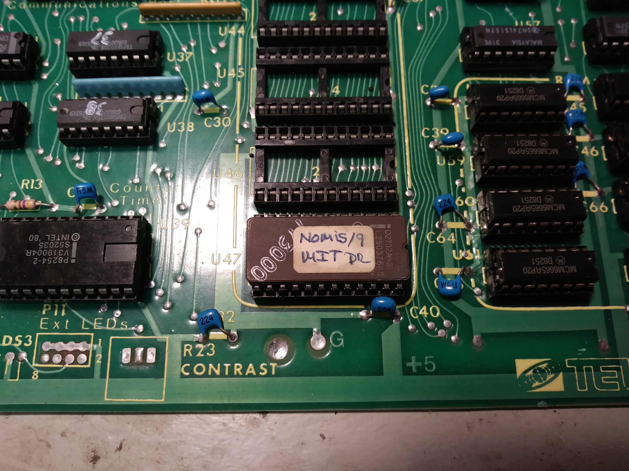
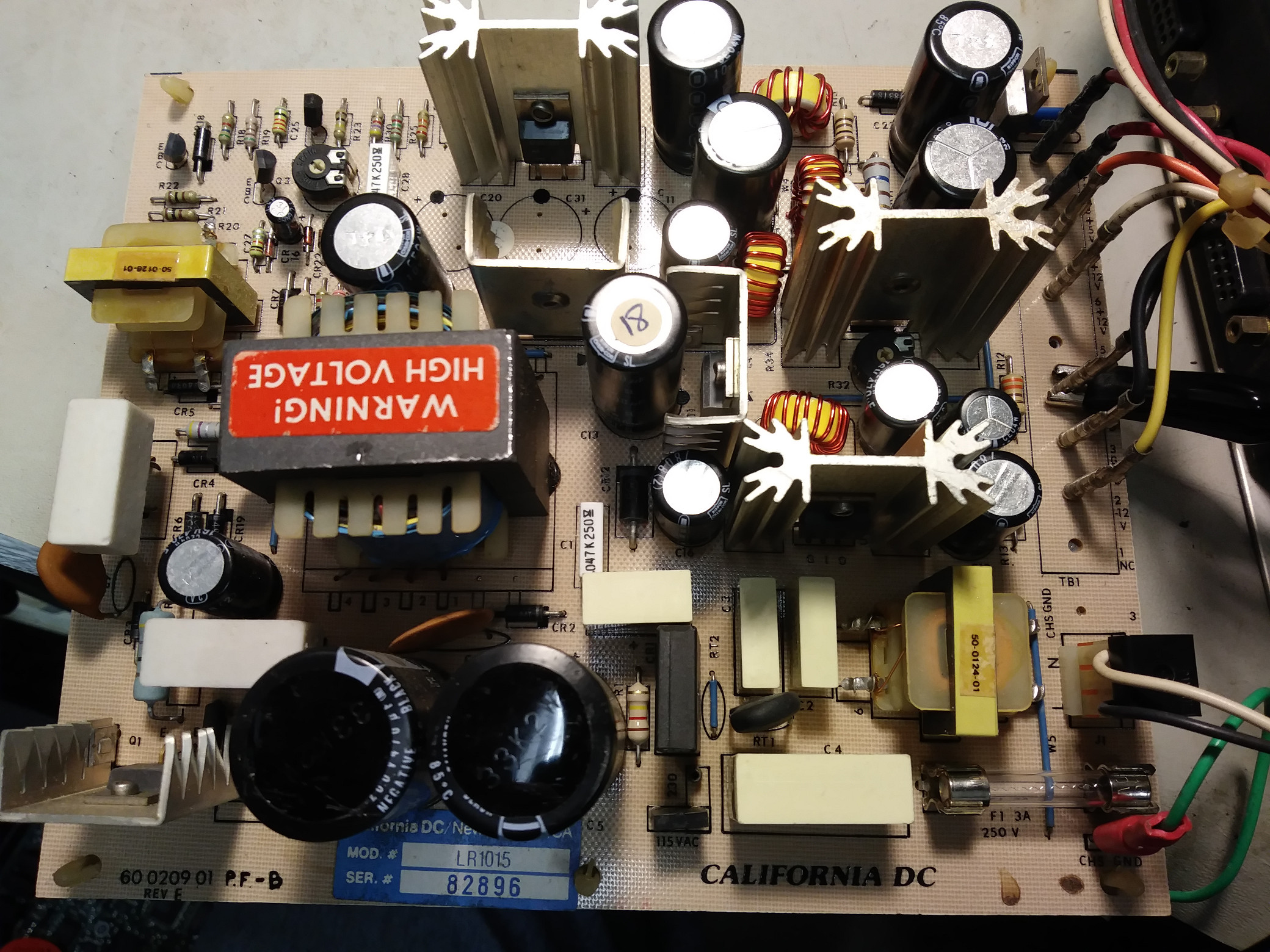
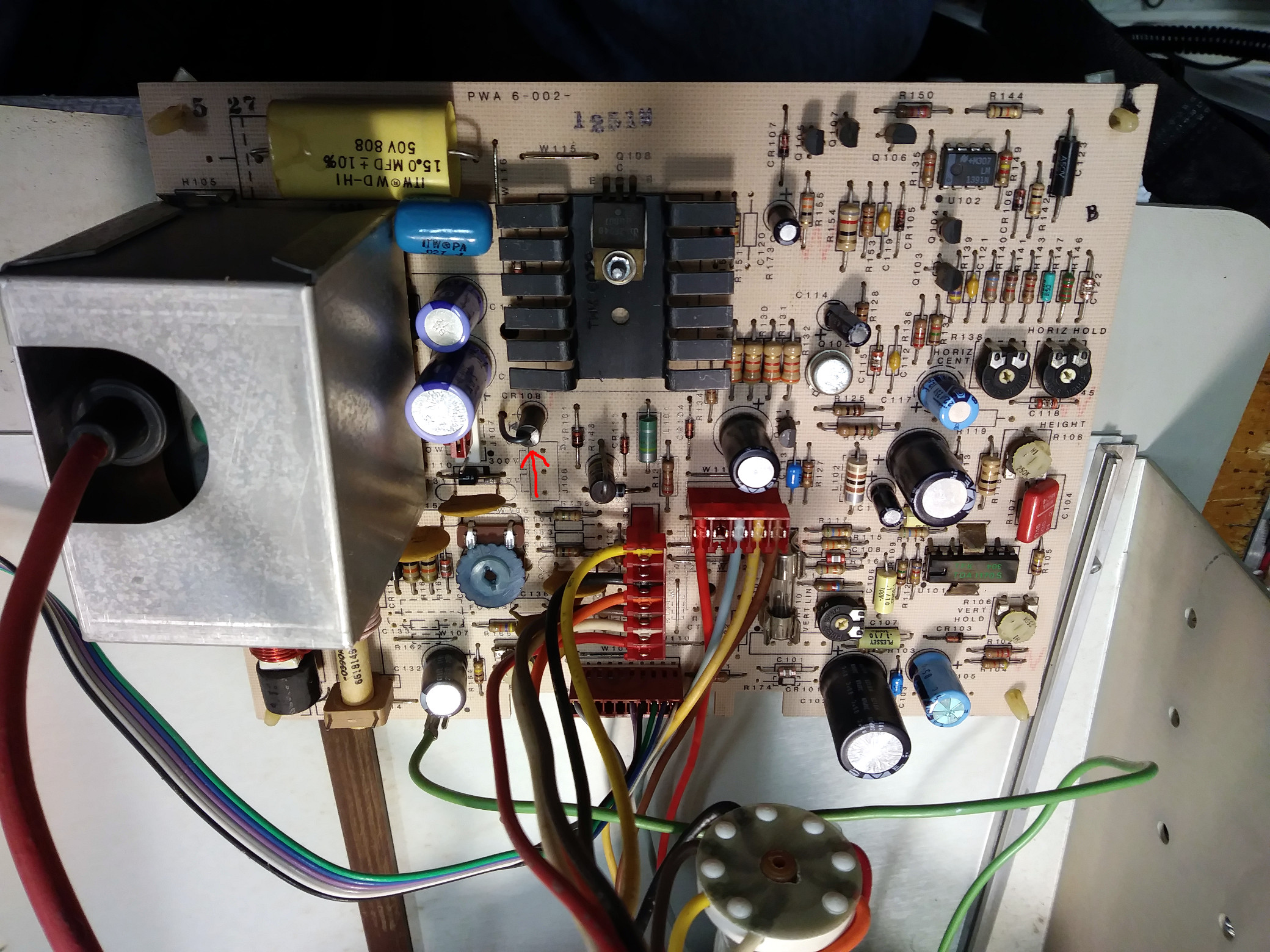
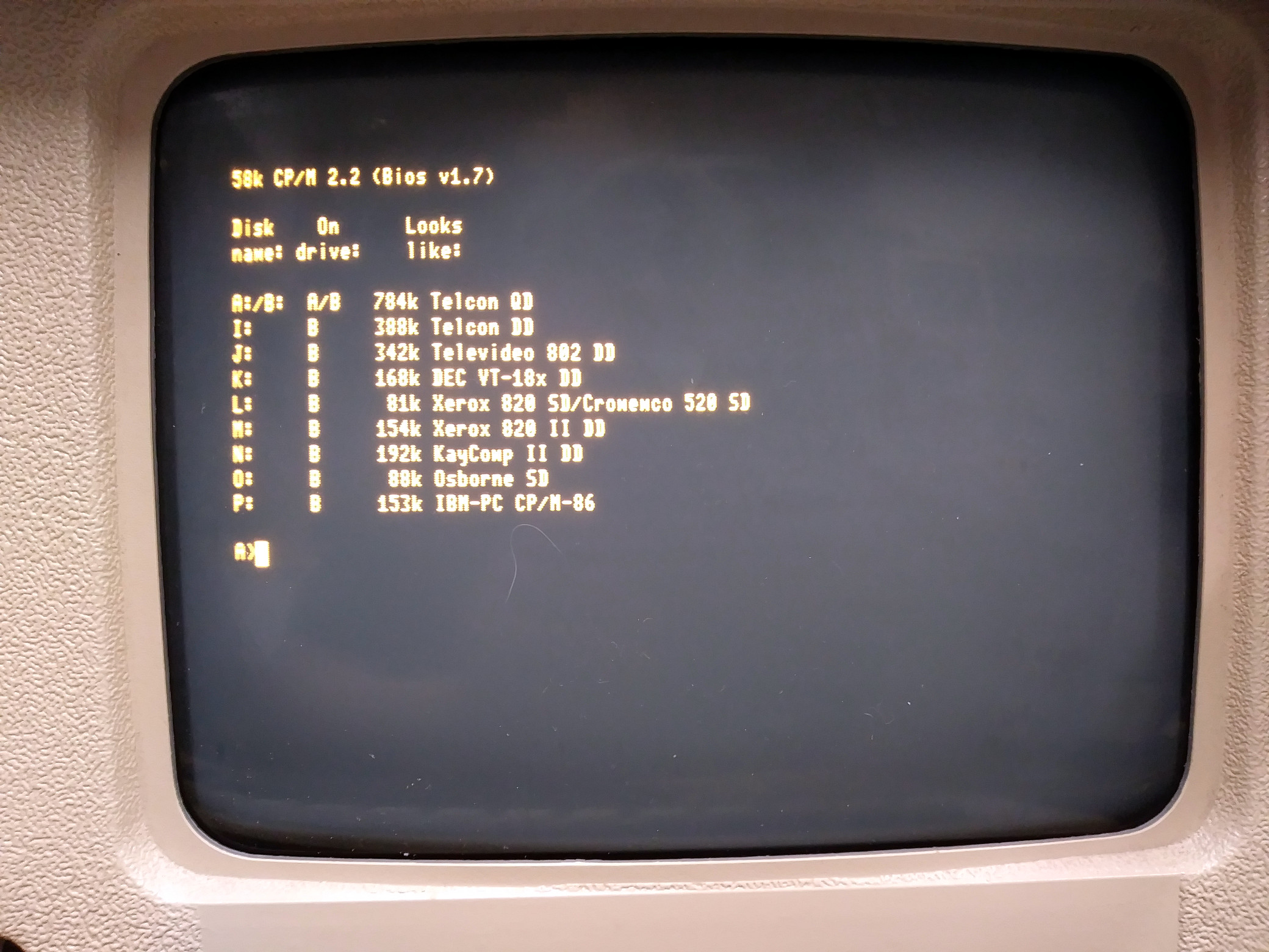
After several extended troubleshooting sessions, my Telcon Zorba (Nomis 9) is up and running! I don't know what happened to this system, but it had some major problems. When I received the system, it did nothing: no lights, no fan, no display. My first thought was a bad power supply, and a voltage check showed that the +12VDC line was down to around 8V. No filament on the CRT, either. Unplugging the display board allowed the 12V line to pop right back up to spec. So, something was wrong on the display board. A visual check of the display board didn't reveal anything obvious. I used my DMM and a curve tracer (connects to my oscilloscope's X-Y inputs) to look for anything odd. I found a large diode which appeared to be shorted. On desoldering it, it just fell apart! No idea what caused it to short, but I ordered some horizontal output transistors just in case. The diode was a MR854 400V 3A fast recovery diode, and the HOT was a BU807. The old HOT tested similarly to the new transistors, but I replaced it anyway. I replaced the diode with an MR856 (600V 3A) for an extra margin of safety. After adjusting the power supply, I plugged everything back together, and bingo, the filament lit up and the 12V line looked good. Still no display though, so I started looking at signals. With the help of the schematics, I traced things back to the CRT Controller chip (CRTC), an Intel 8275 programmable CRTC. No signals coming out of the CRTC at all. I found an Intel P8275 on Ebay, and sat back to wait. After I replaced the the CRTC, the system immediately beeped (which it had never done before), and eventually the boot display came up, telling me to press <ENTER> to boot. A slight tweak on the horizontal hold pot was all it took to stabilize the display. So, second problem solved. However, pressing <ENTER> did absolutely nothing. There was voltage going to the keyboard (the caps lock LED would toggle), but nothing was happening. I checked the output from the keyboard on the scope (looked okay) and from the inverter going to the 8251A USART for the keyboard. Time to haul out the logic analyzer and find out what's happening on the bus. On the diskettes which came with the Zorba, there was one labeled "Gemini Zorba Source BIOS 1.7A". I imaged the disks with IMD, and was able to pull the files from them. On the BIOS disk was source code for the CP/M BIOS, as well as source for the boot ROM. I dumped the boot ROM with my Data I/O 29B and ran it through a disassembler (z80dasm). Things didn't quite match up, and it was obvious that the ROM in my Zorba wasn't exactly the same as on the disk. Working with z80dasm on the Linux side and Z80ASM on the CP/M side, I was able to create an ASM file which assembled and loaded to an exact copy of my Zorba's boot ROM. Armed with the correct assembly listing, I hooked up the logic analyzer HP (1650B) to see what was happening. The code was stuck in a loop, waiting for the floppy drives to home to track 0. The heads would move (if initially off of track 0), but the code was waiting for an interrupt from the FDC (1793) which never happened. I started checking the circuitry for the interrupt chain, and found a shorted 2N3904. After I replaced it, the code moved on, but again was looping, this time waiting for the keyboard. I initially thought the USART for the keyboard was bad, but swapping it with another 8251A on the board didn't change anything. A check of the signals going to the USART showed the proper select lines activating, but the RxRDY line never showed a character ready. I finally checked the clock line for the USART. The frequency should have been 19,230Hz, but was nowhere close. The clock comes from an 8254-2 Programmable Interval Timer, which has 3 independent counters. The 8254 is programmed early in the boot process, and counter 3 takes the 8MHz clock and divides it by 416 to provide the TX/RX clock for the keyboard USART. The USART then divides the 19,230 clock by 16 to provide something close to the 1200 baud clock for the keyboard. The logic analyer showed the correct programming sequence going to the 8254, but only random values were coming out. So, back to the order form for a couple of 8254-2 chips and some other spares for inventory. As soon as I replaced the 8254 (actually with an 82C54-2) the frequency counter showed 19,230 from counter 3, and the keyboard magically came to life. It booted! This is the most difficult micro fix I've ever had to make. The tally of bad components reads:
I ended up using the following test equipment to find the problems:
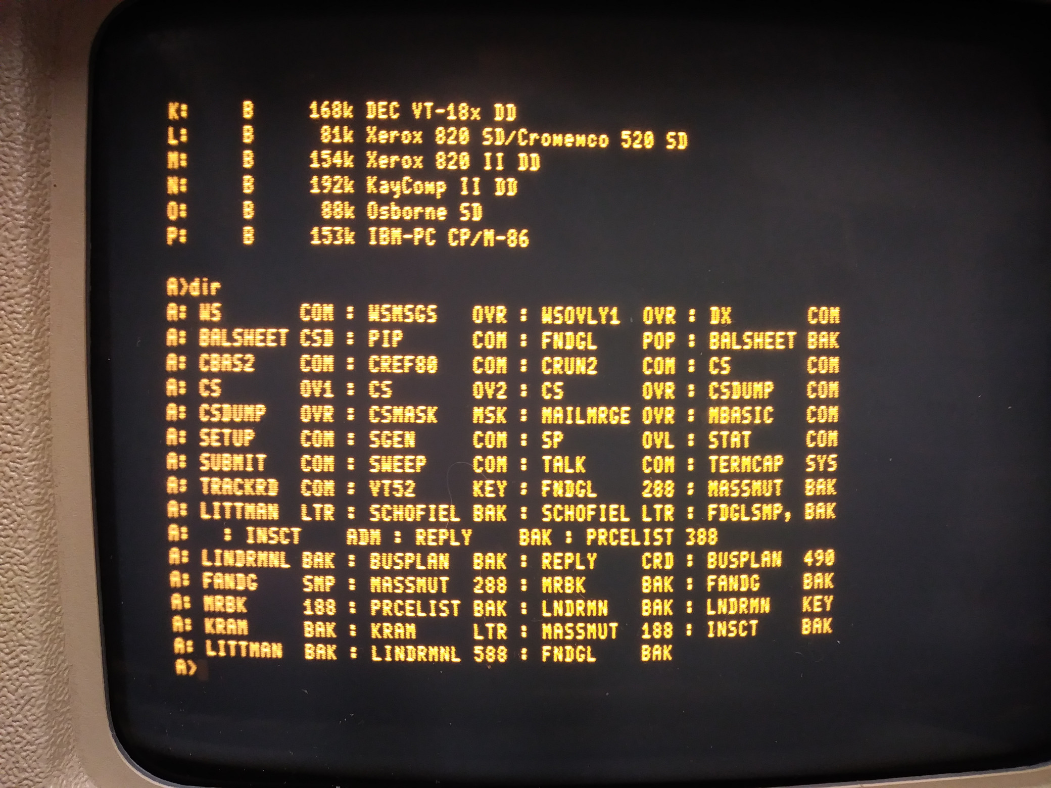
I also wasted some time chasing imaginary floppy drive problems. To simplify things, I was only using a single floppy drive. After chasing code with the logic analyzer and the source listing, I discovered that whoever wrote the boot ROM code decided to wait for BOTH floppy drives to interrupt when they reached track 0 before moving on. If one of the drives is bad, or not installed, the code will loop forever waiting on the bad/nonexistent drive. All told, it was an interesting journey, and I now know more than I ever wanted to know about the Zorba. :-) As of 03/31/2020, the system no longer boots from diskette. Read error on track 0, sector 1. |
![]()
![]()